


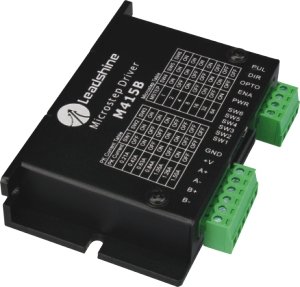
New Leadshine M415B Stepper Drives work
Features:
- High performance, low cost
- Supply voltage up to +40VDC
- Output current up to 1.5A
- Inaudible 20 KHz chopping frequency
- TTL compatible and optically isolated input signals
- Automatic idle-current reduction
- Mixed-decay current control for less motor heating
- 7 selectable microstep resolutions: 1, 2, 4, 8, 16, 32, 64
- Suitable for 2-phase and 4-phase motors
- Protection against power leads(+, -)reversal
- Small size: 86*55*20mm (3.386*2.165*0.787Inch)
Introduction :
The M415B is a very small size high performance microstepping drive based on one of the most advanced technologies in the world today. It's suitable for driving any 2-phase and 4-phase hybrid stepping motors. By using advanced bipolar constant-current chopping technique, it can output more speed and power from the same motor, compared with traditional drives such as L/R drives.
Specifications :
General :
Electrical Specifications (Tj = 25oC/77oF)
|
Parameters |
M415B |
|
Supply voltage |
+15 to 40 VDC |
|
Typical supply voltage |
+24-+36 VDC |
|
Output current (Peak) |
0.21 to 1.5 A |
|
Microstep resolutions |
1, 2, 4, 8, 16, 32, 64. |
Connector P1 Configurations
|
Pin Function |
Details |
|
PUL |
Pulse signal: This input represents pulse signal, effective for each rising edge; 4-5V when PUL-HIGH, 0-0.5V when PUL-LOW. For reliable response, pulse width should be longer than 1.5ms. Series connect resistors for current-limiting when +12V or +24V used. |
|
DIR |
Direction signal: HIGH/LOW level signal, correlative to motor rotation direction. For reliable response, DIR must be ahead of PUL by 5ms at least. 4-5V when DIR- HIGH, 0-0.5V when DIR-LOW. Motor rotation direction also depends upon the connection of the motor windings, exchange any motor phase can reverse motor rotation direction. |
|
OPTO |
Opto-coupler power supply, and the typical voltage is +5V. |
|
ENA |
Enable signal: This signal is used for enabling/disabling drive. High level for enabling drive and low level for disabling drive. Usually left unconnected (enabled). |
Connector P2 Configurations
|
Pin Function |
Details |
|
Gnd |
DC power ground |
|
+V |
DC power supply, 15~40VDC, Including voltage fluctuation and EMF voltage. |
|
A+, A- |
Motor Phase A |
|
B+, B- |
Motor Phase B |
Selecting Microstep Resolution and drive Output Current

This drive uses a 6-bit DIP switch to set microstep resolution, and motor operating current, as shown below:
Microstep Resolution Selection
Microstep resolution is set by SW4, SW 5, SW 6 of the DIP switch as shown in the following table:
Microstep |
Steps/rev.(for1.8o motor) |
SW4 |
SW5 |
SW6 |
|
1 |
200 |
ON |
ON |
ON |
|
2 |
400 |
OFF |
ON |
ON |
|
4 |
800 |
ON |
OFF |
ON |
|
8 |
1600 |
OFF |
OFF |
ON |
|
16 |
3200 |
ON |
ON |
OFF |
|
32 |
6400 |
OFF |
ON |
OFF |
|
64 |
12800 |
ON |
OFF |
OFF |
Current Settings
|
Peak current (A) |
SW1 |
SW2 |
SW3 |
|
0.21A |
OFF |
ON |
ON |
|
0.42A |
ON |
OFF |
ON |
|
0.63A |
OFF |
OFF |
ON |
|
0.84A |
ON |
ON |
OFF |
|
1.05A |
OFF |
ON |
OFF |
|
1.26A |
ON |
OFF |
OFF |
|
1.50A |
OFF |
OFF |
OFF |
Note: Due to motor inductance, the actual current in the coil may be smaller than the dynamic current settings, particularly under high speed condition.
Typical Connections

Mechanical Specifications (unit = mm [inch]) :

ราคา 1700 บาท สินค้าหมดชั่วคราว