


arduino with TCS230
Pin definition and working principle
Pin definition


Working principle

As we know, according to the RGB color model, a broad array colors is produced by red green and blue light added together in various ways. In other word, if we know the RGB data which constitutes different kind of color, we can get the certain color we test. With a certain color filter is selected(e.g red filter), TSC230 color sensor allows red light to get through alone and prevent other color green and blue light, so we can get the intensity of the red color. Blue and green light of intensity can be got in the same way.

TCS230 includes 8X8 array of photodiodes, 16 photodiodes have blue filters, 16 photodiodes have green filters, 16 photodiodes have green filters and 16 photodiodes are clear with no filters. With the different combination of S2 and S3, we can choose different type of color filter The full-scale output frequency can be scaled via two control input S0 and S1, by which we can output the different frequency coefficient (100%, 20%, 2%).


Product Description
- Chip: TCS230
- Input voltage: DC 3V-5V
- Output frequency voltage: 0 ~ 5V
- Use bright white LED lights
- can be connected directly with Microcontroller
- Static detection of the measured object color
- Best detection distance: 10mm
ราคา 350 บาท

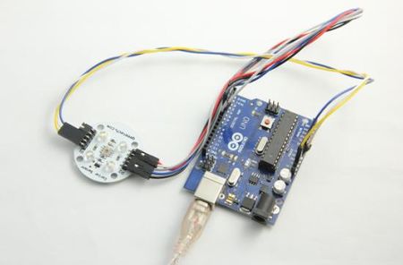
Wiring diagram
Here is the guide illustrates how to connect an Arduino to TCS230 Color Recognition Sensor module. The following is a table describing which pins on the Arduino should be connected to the pins on the TCS230 Color Sensor:


Example code
int s0=3,s1=4,s2=5,s3=6;
int flag=0;
int counter=0;
int countR=0,countG=0,countB=0;
void setup()
{
Serial.begin(115200);
pinMode(s0,OUTPUT);
pinMode(s1,OUTPUT);
pinMode(s2,OUTPUT);
pinMode(s3,OUTPUT);
}
void TCS()
{
  digitalWrite(s1,HIGH);
  digitalWrite(s0,LOW);
  flag=0;
  attachInterrupt(0, ISR_INTO, CHANGE);
  timer2_init();
}
void ISR_INTO()
{
  counter++;
}
void timer2_init(void)
{
  TCCR2A=0x00;
  TCCR2B=0x07; //the clock frequency source 1024 points
  TCNT2= 100;    //10 ms overflow again
  TIMSK2 = 0x01; //allow interrupt
}
int i=0;
ISR(TIMER2_OVF_vect)//the timer 2, 10ms interrupt overflow again. Internal overflow interrupt executive function
{
TCNT2=100;
flag++;
if(flag==1)
 {
   counter=0;
 }
else if(flag==2)
  {
   digitalWrite(s2,LOW);
   digitalWrite(s3,LOW);
   countR=counter/1.051;
   Serial.print("red=");
   Serial.println(countR,DEC);
   digitalWrite(s2,HIGH);
   digitalWrite(s3,HIGH);
  }
else if(flag==3)
   {
    countG=counter/1.0157;
   Serial.print("green=");
   Serial.println(countG,DEC);
    digitalWrite(s2,LOW);
    digitalWrite(s3,HIGH);
    }
else if(flag==4)
   {
    countB=counter/1.114;
   Serial.print("blue=");
   Serial.println(countB,DEC);
    digitalWrite(s2,LOW);
    digitalWrite(s3,LOW);
    }
else
    {
    flag=0;
     TIMSK2 = 0x00;
    }
    counter=0;
    delay(2);
}
void loop()
{
 delay(10);
 TCS();
 if((countR>10)||(countG>10)||(countB>10))
  {
     if((countR>countG)&&(countR>countB))
      {
           Serial.print("red");
           Serial.print("\n");
           delay(1000);
      }
     else if((countG>=countR)&&(countG>countB))
      {
           Serial.print("green");
           Serial.print("\n");
           delay(1000);
      }
    else if((countB>countG)&&(countB>countR))
     {
           Serial.print("blue");
           Serial.print("\n");
          delay(1000);
     }
   }
 else
 {
    delay(1000);
 }
}
