


arduino กับการวัดกระแส ACS712 module
บางครั้งในการทำงานของระบบไฟฟ้าเราจำเป็นที่จะต้องการทราบถึงกระเเสไฟฟ้าที่ไหลในวงจรหรือ กระแสไฟฟ้าบางจุดดังนั้น
ในวันนี้เราจะมาทำการวัดกระแสโดยใช้ ACS712
โครงสร้างภายใน IC ACS712
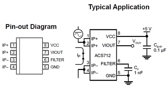
ซึ่งจะเห็นได้ว่าโครงสร้างภายในไม่ยุ่งยาก
แต่วันนี้เรามีเป็นแบบ module ที่งานในการใช้งาน
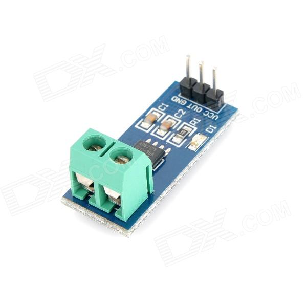
การต่อ module acs712 เข้ากับตัว arduino board ให้ต่อตามวงจรด้านบนสุดนะครับจะเห็นได้ว่าไม่ยุ่งยากเลย ส่วนขา mesure เราก็นำไปต่อกับ load ครับ
load ของเรา อาจจะเป็น motor หรือ หลอดไฟครับให้ต่อ อนุกรมกับตัววงจรครับ
ตัวอย่าง code arduino
int analogInPin = A1; // Analog input pin that the carrier board OUT is connected to
int sensorValue = 0; // value read from the carrier board
int outputValue = 0; // output in milliamps
void setup() { // initialize serial communications at 9600 bps:
Serial.begin(9600); }
void loop() {
// read the analog in value:
sensorValue = analogRead(analogInPin);
// convert to milli amps
outputValue = (((long)sensorValue * 5000 / 1024) - 500 ) * 1000 / 133;
/* sensor outputs about 100 at rest. Analog read produces a value of 0-1023, equating to 0v to 5v. "((long)sensorValue * 5000 / 1024)" is the voltage on the sensor's output in millivolts. There's a 500mv offset to subtract. The unit produces 133mv per amp of current.*/
// print the results to the serial monitor:
Serial.print("sensor = " );
Serial.print(sensorValue);
Serial.print("\t Current (ma) = ");
Serial.println(outputValue);
// wait 10 milliseconds before the next loop
// for the analog-to-digital converter to settle // after the last reading:
delay(10); }
จาก code ตัวอย่างนี้ ให้ดู output ที่ serial monitor ซึ่งสามารถตั้งค่าต่างๆให้กับตัวโปรแกรมได้ อธิเช่นเมื่อมีกระแสเกินที่เรากำหนดให้ เกิดสัญญาณเตือน